VM-1S
voice modular
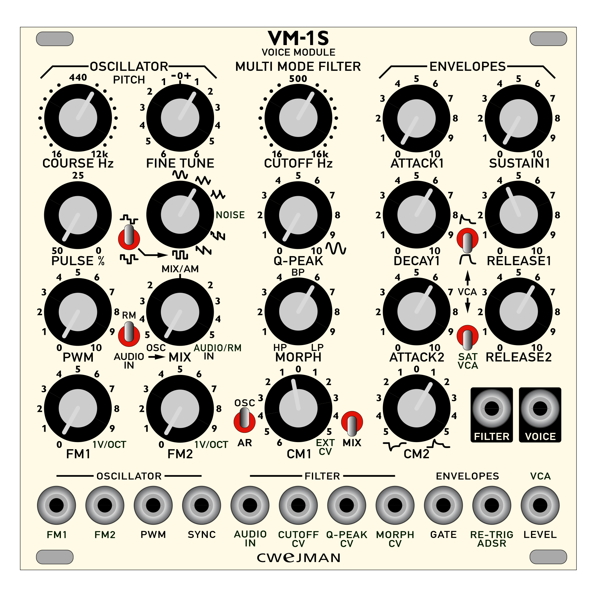
OSCILLATOR
COARSE and FINE TUNE are the main controls for pitch of the oscillator, modulated by two
different FM signals with independent control, FM1 and FM2, both controls are calibrated for 1V/OCT when potentiometer controls are both to max.
WAVEFORM selector let you choose the oscillator waveform, and from top to bottom waveforms are: sine, triangle, triangle mixed with sawtooth, white noise, square mixed with sawtooth and square, the pulse shape of the pulse rate percent of the square wave can be decided with its dedicated switch, the pulse rate percent goes from 50% to 0%, and it’s controlled by PULSE % potentiometer.
PWM of square wave can be modulated by external cv with PWM cv and has its attenuator called PWM.
You can also sync oscillator frequency with SYNC jack in.
MIX control let you choose the source for the MULTI MODE FILTER, on the left position you have the main oscillator, waveform is selected from the rotary switch above the mix control, on the right position, you have 2 possible options, selected by the switch on the left of MIX control, and are RM ( ring modulation achieved from sine of the main oscillator and AUDIO IN signal ) and AUDIO IN, in the middle position of MIX control you have AUDIO MODULATION between main oscillator and AUDIO IN or RM with AUDIO IN signal.
MULTI MODE FILTER
CUTOFF Hz is the main frequency control of the filter, with his own CUTOFF CV input and 2 different modulation inputs:
- CM1, this pot let you choose the first modulation input of filter cutoff, on the left side of the control the switch let you choose the source of the left side of the CM1 pot, which are OSC, oscillator sound source, or AR, which is the 2 stages envelope, ATTACK2 and RELEASE2. On the left side of the pot the source of the modulation is the CUTOFF CV in, which is also calibrated for 1V/OCT, the MIX switch changes the behavior of the CM1 potentiometer, when it is activated you mix the OSC/AR signal and EXT CV signal, if it’s not activated when the pot is in the middle you don’t have any modulation at all, it works as 0 position for the 2 modulations of the control.
- CM2 is the cutoff modulation from the ADSR envelope and can be selected as negative ( left position ) or positive ( right position ).
Q-PEAK is the Q ( resonance ) control and has its own cv input.
MORPH control let you mix the filter mode between High Pass, Band Pass and Low Pass and has its own cv input.
You can hear the filter signal not processed by VCA on the FILTER output.
ENVELOPES
There are 2 different envelopes available, a four stage envelope with ATTACK, DECAY,
SUSTAIN and RELEASE controls, a 2 stages envelope with ATTACK and RELEASE controls.
You can choose which one will act as control on the main vca with the dedicated switch which is located between the 2 envelopes control.
Both envelopes has the same gate sources, which are GATE jack input and RE-TRIG jack input
VCA
Vca has a switch that can overdrive the output signal, it is called SAT, main vca output is VOICE output jack, and can be modulated by vca level jack input
+115mA
-110mA